The Santa Claus Problem - A Tutorial in CDL
This article describes a CDL solution to John Trono’s ‘Santa Claus’ concurrency problem [1]. It is primarily intended as an introductory tutorial and does not assume any familiarity with CDL. The example illustrates an alternative to conventional threading and also explains a methodical incremental process for migrating existing sequential applications to a parallel environment.
Readers that are familiar with CDL could therefore skip the overview, symbolism and event flow sections. The example solution is not optimal in any sense and is primarily contrived to introduce the basic concepts of the Concurrent Description Language (CDL).
CDL OverviewCDL is a machine translatable Visual Programming Language (VPL) which allows developers to describe a concurrent application’s communication and synchronization logic in a localized contiguous manner (logic is not dispersed through files). It adopts an event based paradigm and calls user specified textual code in response to the arrival of specified event patterns. So creating CDL applications is rather like creating GUI applications using a form designer; the framework is visual, the ‘handler functions’ are textual. It is object-oriented in the sense that it supports notions of encapsulation, aggregation, inheritance and abstract definition. Applications are composed from one or more ‘circuits’ (concurrent equivalents of classes), and these are constructed from the composition of object and connection primitives, and in some cases, the overriding of their default behavior through attribution. CDL abstracts the platform and so can be executed in any multi-threaded and/or distributed hardware environment (to which the runtime has been ported). Translated code is linked with CDL’s runtime which provides discovery, scheduling and other services. The Problem
On the face of it the problem appears fairly simple, but turns about to be surprisingly difficult to solve using counting semaphores and exclusion alone. Comparison with other solutions can be drawn from [2] which provides a polyphonic C# solution, [3] which provides ADA95 and Java solutions, and [4] which provides a pseudo-C semaphore based solution.
Nick Benton [2] states the problem as follows;
| Santa repeatedly sleeps until either wakened by all of his 9 reindeer, back from their holidays, or by a group of 3 of his 10 elves. If awakened by the reindeer, he harnesses each of them to his sleigh, delivers toys with them and finally unharnesses them (allowing them to go off on holiday).
If awakened by a group of elves, he shows each of the group into his study, consults with them on toy R&D, and finally shows them out (allowing them to go back to work). Santa should give priority to the reindeer if there is both a group of elves and a group of reindeer waiting. | |
It is worth noting that although Trono’s statement of the problem does not involve the flow of data per-se, the techniques used in this solution are similar to those that would be required to solve general message filter problems. Symbolism
Before describing the solution itself, this section provides a very brief description of the subset of CDL objects utilized for the example problem. A more comprehensive description [5] is given at the URL at the end of this document.
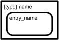
Nodal ObjectsIn CDL, events travel between nodal objects, along connections. Some nodal objects are typed, all have optional instance names (used by the discovery service), and all can be scalar or multi-dimensional. Dimensionality is denoted by one or more pairs of square braces (if omitted, the object is assumed to be scalar).  |
Synchronous semaphores (mnemonic SSM) are directly equivalent to conventional counting semaphores; that is to say that one requester is unblocked for each signaling event delivered to the semaphore. As with most objects, the instance name is optional.
|
 |
Asynchronous semaphores contain a single signed integer which can be modified by signalers. Consumers can specify ‘keys’ and ‘rules’. For example, the consumer may wish to block until the semaphore value exceeds 24, or is equal to 15 and so on. These objects are primarily provided as a means of providing switching and routing logic (equivalent to conditional branching).
|
 |
Arbitrated stores (mnemonic AST) are repositories for persistent shareable data. These provide various blocking/non-blocking arbitration schemes but for this example we are going to use them in a mode that will cause them to notify all their connectees each time they are updated. This provides a simple broadcast-able triggering mechanism that will unblock all waiters each time we write to the store, or if the store has been updated at least once since their last request, continue without blocking. This is similar to a publish/subscribe pattern. In this example all stores have data_type void (no actual data content) but the act of ‘updating’ is sufficient to trigger the notification.
|
 |
Synchronous stores (mnemonic SST) are repositories for transient data (buffers are re-cycled when no longer referenced) and so all reads are ‘destructive’. It is frequently the case however that store data needs to be provided to multiple consumers, and in this case the store is simply coupled with a distributor (see below). Again, for this case all stores are actually ‘data-less’ and are simply being used for synchronization purposes.
|
 |
Collectors (mnemonic CLX) can be thought of as logical ‘AND’ gates. Any number of connections can be made to the ‘collecting’ face (bold straight face), and when all of the events have arrived, a single ‘compound’ event is provided to the consuming object, which is connected to the collector’s providing face (round face). Collections are nestable in the sense that compound events can themselves be collected. In random collection mode, events are simultaneously requested and collected in arrival order; in sequential mode, events are collected in the specific order indicated by the collection face indicator.
|
 |
Distributors (mnemonic DBX) can be thought of as broadcasting each consumed event, to each connected consumer. The consumed event could be an atomic or compound event and remains open until the last consumer has indicated completion by closing. This provides CDL with an equivalent of automatic ‘stack’ data and enables composable ‘thread-safe’ communication by reference.
|
 |
Multiplexors (mnemonic MPX) can be thought of as logical ‘OR’ gates, and any event retrieved by the consuming face (broad bold face), is immediately delivered to the providing face (opposite point). As with all consuming objects, consumed events can be atomic or compounded. Multiplexors are frequently used as a means of serializing parallel event streams. They can operate in prioritized or round-robin mode. In the former case, multiply available inputs are processed in prioritized order, in the latter case the connections that have been inactive the longest are attempted first.
|
 |
Circuit methods (mnemonic MTHD) execute their specified user code each time their input/output event patterns are provided. They can have automatic connections (joined to a bold internal crescent), or manual connections (not joined to a crescent). Methods that have more than one automatic connection will not execute until all automatic connections have received events. Manual connections are under explicit user code control, whilst automatic connections propagate circuit generated events. Methods also have a ‘type’ which enables them to be defined once but instantiated many times.
|
 |
CDL does support the notion of a thread (mnemonic THRD), but in practice they are seldom used for anything other than external I/O. Circuit methods make more efficient use of system resources, and since their implementation avoids the expense of operating system context switching, threads are only required when control blocks outside of CDL. The example problem does not perform any device I/O but threads are included here for completeness.
|
 |
Finally, circuits can be thought of super classes which are formed from interconnected aggregations of all the formerly described objects (and sub-circuits). The principal purpose of circuitry then is to describe how method and thread invocations are scheduled and synchronized. The example circuitry can therefore be thought of as constraining the execution of Santa,. and his reindeer and elves; to be that prescribed by the problem. Circuits, like methods, are re-usable through the notion of ‘type’
|
 |
The abstract consumer gives CDL an abstraction for any event consuming object or object tree. The constraints on its resolving circuitry are generally implied by the event or event tree that it logically consumes. These are used in prototype definitions.
|
 |
The abstract provider is similar to its consuming equivalent (in fact they can be merged into a single symbol on occasions. Again there are constraints on their resolving circuitry which are now dictated by the event or event tree that they logically provide.
|
 |
The abstract active object is used in prototypes to indicate connection to an active object which typically provides signals to CDL semaphore objects.
|
ConnectionsJust as sequential text descriptions derive their meaning from statement choice, and statement order; CDL descriptions derive their meaning from nodal object choice, and the connectivity between them. It is therefore analogous in some ways to electronic engineering (pulses traveling through wires and events traveling along connections). In fact, this could be taken one step further because modern digital electronics involves programmable logic devices (most conveniently programmed in VHDL etc), whilst CDL involves programmable methods (most conveniently programmed in various high-level source languages).
Event flow direction is implicit from nodal object symbolism but it is necessary to indicate the direction of signals and notifications, and to differentiate between reads, writes and updates (see Event Model below). The example utilizes two types of events. Firstly there are events which originate from repository objects (stores and semaphores), and secondly ‘notifications’ which are generated in response to various state changes (e.g. AST being updated).
CDL also supports the notion of a ‘bus’ (see Figure 1) and these are indicated by bold lines. Each connection attaching to one side or end of a bus is considered to be connected to all connections on the opposite side or end of the bus. Buses are provided to assist legibility. 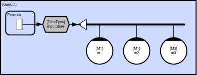
Figure 1 - Example of a bus
ReferencesReferences provide a means of connecting to remote public CDL objects (instantiated in adjacent circuits). All CDL objects have unique path names and at runtime the discovery services locates and connects the target object which could be in the executing process, or belong to any other process in the application. References can use absolute or relative schemes. This could be used to ‘call’ a sub-circuit which is located on a remote machine, or subscribe to some remote event stream and so on. In the example circuit however, there is a local reference which simply keeps the diagram tidy by avoiding crossed connections. 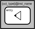
Figure 2a - Absolute referencing
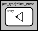
Figure 2b - Relative referencing
Joined-Up CDL
Although a full description is beyond the scope of this example, the full CDL symbolism provides a number of ‘shorthand’ abbreviations. The example solution makes extensive use of the ‘implicit’ method collector notation. Consider the simple case of a method which collects two stores; reading a single input and writing a single output. This is illustrated in Figure 2 (in longhand and shorthand CDL respectively). In the case of random collection, both crescents have the same size but in the case of ordered collection, the larger crescent’s connections are collected first.
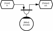
Figure 3a - Long-hand (explicit) collection
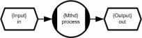
Figure 3b - Short-hand (implicit) collection
CDL also supports the notion of ‘compound objects’. Figure 4 - Collector-Distributor compound object shows a collector/distributor pair. The inference here is that the distributor inherits the instance name, scope and dimensionality attributes of the named object (the collector). This means that all compound events provided by the collector will be distributed to each consumer that connects to the distributor. 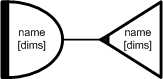
Figure 4a - Long-hand (separate) Collector and Distributor

Figure 4b - Short-hand (joined) Collector and Distributor
Language Equivalence
As mentioned earlier, CDL circuits (and methods) can be thought of as concurrent equivalents of conventional classes. This section explains this property in a little more detail, and should therefore give a clearer understanding of the OO nature of CDL. Having the example solution diagram to hand will probably make the following points clearer.
CDL MethodsCircuit method definitions are analogous to classes rather than class member functions. This means that they can have more than one entry point (public member function), and these can share state. So in this example, we can think of the elves as having ‘toy maker’ type (ToyMkr), and two entry points, ‘work’ and ‘consult’ which correspond to the two actions that they perform. The elf method array therefore appears in the circuit twice; firstly when it executes its ‘work’ code, and secondly when it executes its ‘consult’ code. The constraints of the Santa problem mean that these two entry points cannot execute concurrently, but in the general case methods can be reentrant. If two or more entry points do execute concurrently then CDL’s synchronization logic is used to ensure that access to shared state is correctly arbitrated. The ToyMkr method definition is therefore equivalent to the class definition below.
   class ToyMkr
   {
      private:
         ToyMkrState StateObject;   // Private state object;
         ToyMkrState &State();      // Returns ref to current state

      public:
         Uns         Work();        // Work entry point
         Uns         Cnslt();       // Consult entry point
   };
In the example circuit we instantiate an array of 10 toy makers and use instance name ‘Elf’. This is equivalent to the statement; ToyMkr Elf[10]; In practice, the code produced by the CDL translator from circuitry looks very similar to the code above. Like class entry points, circuit method entry points are also prototyped. In the example circuit the ToyMkr prototyping is performed implicitly but if we wanted to define the ToyMkr method as part of a re-usable CDL component library it would be more convenient to prototype it explicitly (rather than imply it by use). 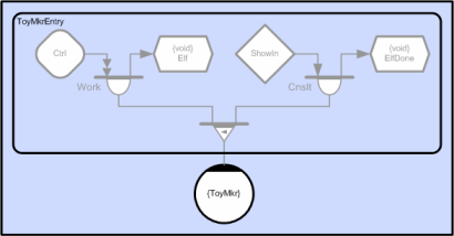
Figure 5 – Explicit ToyMkr Method Prototype
The prototype is interpreted as follows. Each of the ten method elements is shown connected to a multiplexor which implies that it has multiple entry points (analogous to the ToyMkr class with multiple public member functions); in this case two. The left hand branch of the tree (the ‘Work’ entry point) collects two events; the first is an ASM event and the second is an SST ready-for-write of type void (no actual data). The right hand branch of the tree (the ‘Cnslt’ entry point) also collects two events; the first is an SSM event, and the second is also a ready-for-write of type void (see Event Model below).
This tells the translator that whatever object tree we connect to a ToyMkr method instance, it must have leaves that conform to either the Work or Cnslt entry points. In the first case it must contain an ASM event and an SST ready-for-write with data type void; but that is the only connection constraint (it could be an arbitrarily complex object tree made up of CDL primitives such as multiplexors, collectors and distributors). In practice, since this method has data type void (no actual input or output data) we could have been more relaxed and defined the prototype to take any arbitrary event tree as shown in Figure 6. 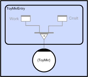
Figure 6 - Relaxed ToyMkr method definition
The method prototype also defines the handler function prototype (code inside the method). In this case it has a single void argument, but in the more general case it will be a list of arguments containing references to input and output data. This mechanism ensures that methods are instantiated and invoked correctly and the translator will generate appropriate errors otherwise. As explained above, each element of the elf toy maker instance could own definitive state (although not required by the Santa problem). In the example circuit, elf element invocations appear in more than one place (diagrammatically) but since they refer to the same method instance (same instance name – ‘Elf’), form logical groups which are referred to as ‘strands’. This is analogous to multiple sequential invocation of the same object element;
   Elf[n].Work();
   // Some statements
   Elf[n].Cnslt();
In the example above the Elf method has two entry points (it appears in the circuit twice), but multiple entry points can also be implied by the use of ordered multiplexors. In this case we can associate a different entry point with each multiplexor link. In the example circuit the Santa method appears three times, but the first of these {Mgr.Wake} is triggered by a tree that either contains a group of reindeer or a group of elves. If an event arrives on the first link, the consuming method {Mgr.Wake} will execute the first entry point (which harnesses the reindeer etc), and if it arrives on the second, it will execute the second (which shows the elves in etc). The translator will therefore generate two separate entry points (the developer must provide code for both) and will transparently execute the appropriate call depending on which event arrives at the multiplexor. This means that the Santa {Mgr} method actually has four entry points;
   class Mgr
   {
      private:
         MgrState StateObject;      // Private state object;
         MgrState &State();         // Returns ref to current state

      public:
         Uns      WakeRdeerGrp();   // If woken by reindeer
         Uns      WakeElfGrp();     // If woken by elves
         Uns      Unharness();      // Unharness reindeer
         Uns      ShowOut();        // Show out elves
   };
Although it is useful to think of each method element as being autonomously executable (having its own thread), the benefit of the circuit method abstraction is that it does not assume that the member methods will actually be executed by the same thread, and in fact, does not even assume that they will be executed by the same machine. In the case that member instances are actually scheduled to different machines, the state object is transparently moved between subsequent invocations by the CDL runtime (this provides topology independence). The ‘colony’ execution model that supports this is discussed in detail in reference [5].
CDL CircuitsIn order to achieve parallel execution we need to schedule two or more methods concurrently. The role of CDL circuitry is to ensure that methods execute in the correct sequence (only run when all inputs and outputs are ready), and also to arbitrate access to shared data. Circuits can also have persistent state. Whilst method state is private, circuit state can be local or global. In the former case it can be shared by all objects within the circuit, and in the second case it can be visible to all adjacent circuits that are within scope. Circuit state is stored in AST objects which also provide the necessary arbitration logic to avoid data races. This means that a given circuit instance can be executed in parallel across two or more networked machines and share data transparently. Circuit definitions (like class definitions) are nestable, and just as classes can own and invoke member objects, circuits can also own and invoke member circuits (relative term sub-circuits). Circuitry is therefore arbitrarily composable which means that concurrency can be compounded. Whilst CDL methods have entry point prototypes which constrain the invoking event tree structure, circuits provide a more general equivalent. This allows circuitry (as well as methods) to be encapsulated and re-used. As with methods, circuits can have any number of entry points and each will have a prototype that is used to generate the correct event marshalling code, and ensure that the circuit (or sub-circuit) is legitimately invoked. The example circuit has a single entry point ‘Ctrl’ which connects to the ‘Start’ ASM. The SantaInvocation circuit (see Figure 7) shows the example circuit instantiated as a sub-circuit and connected to a control method which can switch the Santa circuit on and off by signaling through the entry point. 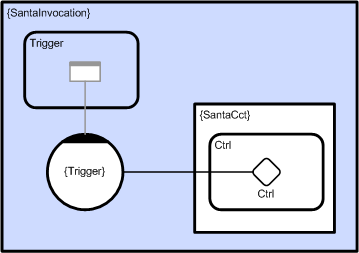
Figure 7 - Invocation of SantaCct
The Event ModelBefore considering the solution in detail, it is necessary to explain CDL’s event model, and in particular, to distinguish between event flow and data flow. Events travel from providing nodes (stores and semaphores) and eventually arrive at consuming nodes (methods and threads) and en route may pass through various event operators (multiplexors, distributors, collectors etc.) which have both providing and consuming connections. In order to keep track of parallel event flow, the CDL debugger uses a color coded convention which enables developers to ‘read’ the current circuit state. In the sections that follow, this has been adopted as a means of describing event flow in general, and illustrating the problem solution in particular. Objects and connections which are blocked (‘closed’) are highlighted in red. Objects and connections which are unblocked (‘open’) are highlighted in green. Objects which have both ‘open’ and ‘closed’ elements appear as amber. Objects and connections which are quiescent (no requests currently issued and no events open) are not colored. We can use this convention to track the progress of events in the example circuit. Consider the simple case of a method which collects two stores; reading a single input and writing a single output. This is illustrated in longhand notation in Figure 8. 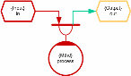
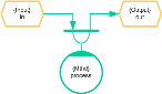
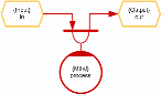
Figure 8 - Method collecting two stores
This example circuit fragment operates as follows. At runtime (and after each activation) CDL methods spontaneously request their trigger events (in this case a collector event), which in turn requests events from each of its connections. In this case it will request a ready-for-read event from the input store and a ready-for-write event from the output store (read/write access indicated by connection arrows). For the purposes of this example we will assume that both stores have been created with one buffer each (the default) but in practice this is an attribute which can be set to any user defined value. Performance can obviously be significantly improved by allocating two or more buffers because this allows chains of two or more methods to execute in parallel (a processing pipeline). The first frame shows the initial situation which assumes that there is no data to read from the input store, but space for one write to the output store. The output store is shown as amber because in the general case there will be a request for read from some other circuitry (not shown here) which means that it is open for write but closed for read (therefore shown as amber). The collector is red because it is still blocked (on the read) and the method is red because it is blocked on the collector. The second frame shows the case after the input store has been written to by some other circuitry that is again not shown. In this case collection has completed and the method is actively executing with its inputs and outputs open. The executing handler function is that specified by the user and must be a function whose arguments match the data types provided by the two stores. The translator will issue an error if the prototypes do not match.
   Uns Mthd::process( Input &in, Output &out )
   {
     // User code populates ‘out’ reference using data from ‘in’.
     // Returning from this call will propagate ‘out’ to the next
     // processing stage (which takes ‘out’ as its input data).

     return TRUE;
   }
Both stores are shown as amber because typically (for single buffered stores) the input store will have a consumer waiting to write to it, and the output store will still have a consumer waiting to read from it. Both stores will therefore have one open (green) connection, and one closed (red) connection but in this fragment the closed (red) connections are not identified. The third frame shows the case after execution. When the ‘process’ call returns the collector is automatically closed which in turn closes all of its currently consumed events. Closing the input store returns the readable buffer (which then becomes writeable), and this may of course unblock some earlier consumer that was blocked waiting to write to the input store. Conversely, closing the output store returns the writeable buffer (which then becomes readable), and may also unblock some other consumer who was blocked waiting to read from the output store. The method then automatically re-requests from the collector which in this example is assumed to block because its input store is assumed to be opened by an activated writer, and its output store is assumed to be opened by an activated reader. The detailed explanation above might seem a little complicated but the net result is just a stream of data arriving at a method, which applies its transfer function, and produces a stream of output. This is directly equivalent to calling a function with (in this simple example) one input argument and one output argument. Conceptually, this means that whilst read data-flow is away from the store, and write data-flow is toward the store, ready-for-read and ready-for-write events both flow out from a store. This distinguishes event flow from data flow and is an important distinction. The Santa Solution
The complete solution is comprised from three elements; the symbolism in the diagram, source text for method execution, and attribute settings for nodal objects and connections. In order to follow the description below, we recommend having the example solution visible somewhere.
The example problem has three active participants; Santa (who manages), the reindeer (who deliver), and the elves (who make toys). Stage 1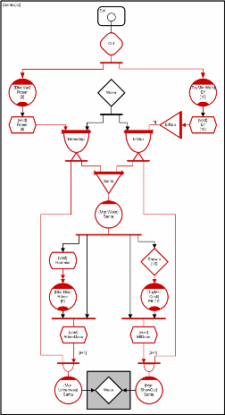
When the illustrated circuit first executes, all automatic method connections will issue event requests and these will propagate through the circuitry (from consumer to provider). Although there are a number of SSTs which are empty, in every example case collection is sequential, with writes requiring earlier events. At this stage none of the collections can progress as far as their write requests and all objects are therefore blocked. The reindeer’s ‘vacation’ methods and the elves ‘work’ methods are initially blocked waiting for the Ctrl ASM to be set to one. In order to trigger circuit iteration we therefore need to write ‘1’ to the ‘Ctrl’ ASM. This could be done from circuit initialization code, or more typically from a GUI callback. Once the ASM has a value of ‘1’ execution will continue indefinitely until paused by a subsequent write of ‘0’. The ‘Wake’ SSM is created with an initial count of ‘1’ and will therefore be available to the first request. Stage 2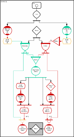
The illustrated state assumes that the Ctrl ASM has been signaled and that all reindeer and elf methods have collected their ready-for-writes and become executable. It also assumes that the nine reindeer have been on holiday and returned but the elves are still working. The RdeerGrp CLX has collected all 9 Rdeer SST read events as well as the Wake semaphore event. This compound event has been distributed to the Santa MPX and the anonymous collector that is connected to the Santa unharness method (bottom left). The Santa MPX has provided this compound event to the Santa Wake entry point and so Santa is currently harnessing the reindeer. At this stage the Santa unharness entry point still cannot run because it is waiting for an event from the RdeerDone SST (the required behavior). The reindeer vacation methods are blocked waiting for Rdeer SST ready-for-writes (being harnessed). Stage 3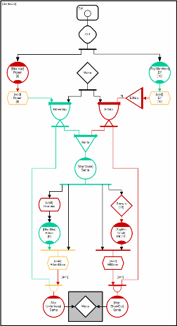
The illustrated state shows the case where Santa has harnessed the reindeer and he and the reindeer are now delivering toys together. The reindeer were triggered into delivering by Santa’s Wake entry point ‘updating’ the harness AST which then generated a notification to all 10 waiting reindeer delivery methods. The diagram assumes that all ten elves are still working (green). If any of the elf methods had completed working then they would now be blocked (waiting to be shown in by Santa in groups of 3). Note that it is the [3] on the right hand ElfGrp collector connection which specifies that the collector must acquire 3 ElfGrp multiplexor events. This therefore determines the ushered group size. This means that the logical concurrency at this stage is somewhere between 10 (all elves finished working) and 19 (all elves still working). The physical concurrency on the other hand depends on the number of available CPUs. By default the runtime will automatically create one software worker thread for each physical CPU core at each utilized method priority (but this can be over-ridden). For performance sensitive applications additional threads can be optionally spawned automatically each time an activated method blocks. In practice, circuit synchronization means that methods very seldom need to block. Method execution tasks are transparently shared between worker threads so more cores just means faster execution. Stage 4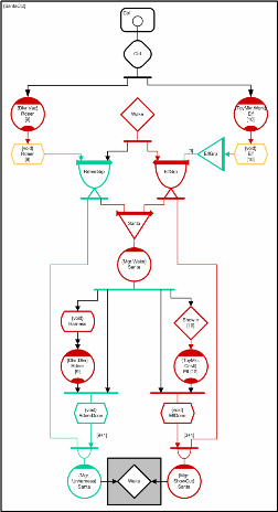
This illustration shows the case where Santa and the reindeer have all completed delivering toys and so the RdeerDone SST has been written-to 10 times in total causing collection to complete and Santa’s unharness entry point to execute. It also assumes that all the elves have now had enough of working and are queued up ready to go in. The first three have been identified but cannot enter until the reindeer are unharnessesed and gone. When Santa’s unharness method signals the Wake SST and exits, they will be able to enter. Stage 5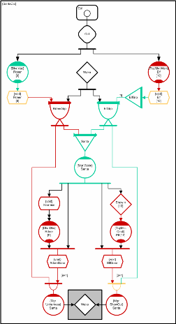
This diagram illustrates the case where Sana’s unharness method has returned and closed its collector. This frees the RdeerDone store for later writes and also closes its distributed connection to the RdeerGrp collector. Since the Santa MPX closed the RdeerGrp collector earlier, both distributed consumers have now closed and so the RdeerGrp collector also now closes. This in turn closes the 10 Rdeer SST elements which then enables the 10 reindeer vacation elements to unblock and sends the 10 reindeer back on holiday. Santa’s unharness method also signaled the Wake semaphore in the last frame which allowed the ElfGrp collector to complete and distribute its event to the Santa Wake method and the Santa show out method (which will not execute yet). At this point the elves have been shown in and Santa is ready to start consultation. The remaining frames are similar to the earlier reindeer equivalents. Handler CodeAs mentioned earlier, since most synchronization is addressed by circuitry which is external to the method code, methods seldom need to block or signal other objects. In fact the Santa problem can be solved without any method signaling at all, but the solution involves more circuitry and it was considered more helpful to provide examples of signaling which could be useful for the more general cases where it is necessary. In practice method initiated signaling is only generally required for the cases where event flow depends on data content. This is not the case for the Santa problem whose event routing only depends on timing. In order to start the circuit executing the Ctrl ASM needs to be set to ‘1’. This requires a connection to the semaphore which is generated by the translator and automatically connected during circuit application initialization. The circuit can be started using; CtrlAsmCxn.Signal( 1 ); The circuit can be paused using; CtrlAsmCxn.Signal( 0 ); The reindeers’ ‘vacation’ entry point simply needs to make a call that executes code (unspecified by the problem) which represents reindeers doing holiday things;
   Uns Dlvr::Vac( void ){
      GoOnVacation();   // Execute reindeer vacation code
      return TRUE;
   }
The elves ‘work’ code is just as straightforward;
   Uns ToyMkr::Work( void ){
      MakeToys();       // Execute elf toy making code
      return TRUE;
   }
The Santa ‘wake’ method is more complicated and because its event tree contains a multiplexor with mixed event types, it can receive two different event types. It therefore requires two separate entry points which perform two different tasks. In the case where the reindeer group arrives before a group of 3 elves (or at exactly the same time), Santa will harness the reindeer to his sleigh and then he and the reindeer will go off delivering toys together. The following code will write to the harness AST which will immediately trigger the reindeer into toy delivery. Santa will then join the reindeer, and when toy delivery is complete, will write to the RdeerDone SST to indicate his completion of toy delivery.
   Uns Mgr::WakeRdeerGrp( void ){
      harnessAstCxn.OpenWrite();       // Harness reindeer
      harnessAstCxn.Close();           // and start them delivering
      DeliverToys();                   // Deliver toys with the reindeer
      rdeerDoneSstCxn.OpenWrite();     // Signal Santa’s completion
      rdeerDoneSstCxn.Close();         // No data to write so just close
      return TRUE;
   }
In the case where a group of elves precedes the group of reindeer, Santa will show the elves into his office and then consult with them on toy R&D matters. The code below assumes that working elves may acquire information while working, which they may wish to use when consulting Santa. This means that information in the elves’ work method elements may need to be shared with the same elements of the elves’ consult method. Santa therefore needs to determine the element numbers of the successful elves so that the appropriate elf elements are consulted. He can do this by extracting link numbers from the 3 elf group multiplexor events that were collected by the elf group collector.
   Uns Mgr::WakeElfGrp( ElfGrpClxEvnt &elfGrpClxEvnt){
      Int elfId;   // Selected elf element number (0 to 9)
      Int i;

      // Interrogate event tree to determine selected elves
      // Usher them in and start them consulting
      for ( i = 0; i < 3; i++ ){
         elfId = elfGrpClxEvnt.elfGrpMpxEvnt[i].LinkNum();
         showInSsmCxn[elfId].Signal(); // Start selected elf
      }
      ConsultWithElves();              // Discuss toy R&D
      elfDoneSstCxn.OpenWrite();       // Signal Santa’s completion
      elfDoneSstCxn.Close();           // No data to write so just close
      return TRUE;
   }
The reindeers’ delivery entry point and the elves’ consultation entry point both just execute application specific delivery and consultation code respectively but Santa’s unharness and ‘show out’ entry points both need to signal the Wake SSM using; WakeSsmCxn.Signal(); // Wake Santa and let in elves or reindeer PrioritizationThe Santa MPX provides the prioritization mechanism. The default behavior for MPXs is to consume from their links in a round-robin manner, but in this case, the Santa MPX uses a prioritized scheme which guarantees that all things being equal, the reindeer link (left hand) will deliver before the elf link (right hand). Even if the 9th reindeer returns from its vacation during elf collection, the reindeer event will preempt and arrive ahead. Summary
The problem circuit contains about 50 nodal and connection objects, about 20 lines of C++ code, and requires about 10 attributes to be set. If we assume that a drag and drop operation takes about the same effort as typing a line of code, then this solution, and those in references [2], [3] and [4] (Ada95, Java, Polyphonic C# and C respectively) are actually comparable in terms of the effort required to create them, and in some sense perhaps, complexity. CDL is machine translatable and we have not included any overhead for pressing the build button!
However, the time taken to conceive a solution, and the time taken to progressively debug it are probably more important metrics (and of course we don’t have them). The point here is that some solutions are more intuitive than others. Although it is clearly subjective, most people do find CDL fairly simple to acquire, and having done so, many feel that it is easier to visualize concurrency than it is to verbalize it. If you are a reader that is being exposed to CDL for the first time, but have prior experience of text languages, you might not be convinced immediately, but will hopefully take familiarity into account. Event flow in particular can seem counter intuitive at first because most developers are more used to thinking in terms of data flow.
The CDL solution does however have a number of implementational benefits [5]. Firstly it is platform independent and is therefore portable. Secondly it is ‘actively’ scheduled and can be executed as one process, or as a load-balanced preemptive colony of dynamically recruitable/retireable processes (e.g. across a network of heterogeneous platforms), without modification. Adding processors at runtime simply makes the application execute faster, and processes can be removed at any stage without loss of data.
The runtime was developed with multi-core in mind and by default the scheduler creates one worker thread, for each CPU, at each utilized method priority, and indeed the example circuit will execute in a single thread. If it is executed on a machine with ‘N’ processors, then it will create ‘N’ worker threads and so on (this can be manually overridden as required but there is seldom any point in doing so). The benefit of dynamic scalability is that performance is optimized for the executing target and the number of threads does not proliferate unnecessarily. If we had to create 20 threads just to execute on a single CPU, performance would suffer (context switching overhead), and we would need to allocate 20 times as much stack data (gratuitously). If we run the same executable on a quad core for example, then the runtime will create 4 threads and execute 4 times as quickly (assuming the same clock speed and ignoring Amdahl’s effects). The Santa Circuit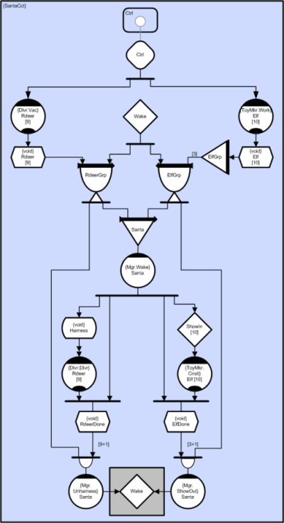
References |